How Are Silicon Wafers Made? 10 Steps From Sand to Polished Wafer
Averroes
Oct 21, 2026
Silicon wafers are made by purifying silicon to 9N electronic-grade polysilicon, growing it into a single-crystal ingot by the Czochralski or float-zone method, and slicing the ingot with a diamond wire saw. Each slice is then edge-profiled, lapped or ground flat, etched to remove saw damage, polished to a mirror finish, cleaned and inspected against SEMI M1 specifications before it ships to a fab.
Wafer manufacturing is Stage 02 of the 12-stage semiconductor manufacturing process. This guide from Averroes.ai, an AI visual inspection platform for manufacturers, maps each step to the specification it sets, the defect it can create and the tool that catches it.
Key Notes
Silicon wafer manufacturing runs in 10 steps, ending in a polished 300 mm wafer about 775 µm thick with total thickness variation under 1 µm.
Each wafering step can create its own defect class: saw marks at slicing, edge chips at edge profiling, scratches and haze at polishing.
Crystal defects such as COPs are set during ingot growth and only become visible on laser scanners after polishing and cleaning.
Laser scanners detect light point defects but cannot always separate particles from pits. Classification sets the false count rate at incoming wafer qualification.
The Wafer Manufacturing Process at a Glance
Silicon wafer manufacturing is the sequence of crystal growth, shaping and surface finishing steps that turns electronic-grade polysilicon into a polished, inspected substrate for chip fabrication. Each step sets at least one specification on the finished wafer. Each step can also leave a defect that a later step has to remove or an inspection tool has to catch.
Wafer manufacturing process: 10 steps
Step
What Happens
Spec It Sets
Defect It Can Create
How It Is Caught
1. Purify
Quartz refined to 9N polysilicon
Purity
Metal and carbon contamination
Lot certification, lifetime test
2. Grow the ingot
CZ or FZ single-crystal pull
Resistivity, oxygen, orientation
COPs, slip, oxygen precipitates
Sample etch, X-ray topography
3. Shape the ingot
Crop, grind, notch
Diameter, orientation
Grinding cracks
Diameter gauge, X-ray orientation
4. Slice
Diamond wire saw cuts wafers
Thickness, initial bow
Saw marks, subsurface damage
Thickness and bow metrology
5. Profile the edge
Grind a rounded bevel
Edge profile
Edge chips, microcracks
Edge inspection
6. Lap or grind
Flatten both faces
TTV, flatness
Residual damage, scratches
Noncontact geometry tools
7. Etch
Dissolve the damaged layer
Damage-free surface
Etch pits, stains
Visual and haze review
8. Polish
Double-side, then final polish
Site flatness, roughness
Scratches, haze, residue
Haze and flatness tools
9. Clean
RCA SC-1 and SC-2
Particle and metal limits
Particles, metal residue
Laser scanner, TXRF
10. Inspect and pack
Final scan, sort, ship
LPD count, geometry
Handling scratches, backside contamination
Laser scanner, edge and backside tools
The diagram makes one point: defects are created at almost every step, but only a few steps carry an inspection that can see them. Most wafering defects are caught at final inspection, long after the step that created them.
Silicon Wafer Manufacturing Process, Step by Step
Silicon wafer manufacturing runs in 10 steps. The first three belong to the silicon ingot stage. Steps 4 to 10 form the wafer manufacturing stage proper, where the ingot becomes individual polished wafers.
1. Purify Silicon to Electronic-Grade Polysilicon
Electronic-grade polysilicon is silicon refined to 9N purity (99.9999999%), used as the feedstock for single-crystal growth. Quartz is first reduced to metallurgical-grade silicon in an arc furnace. That silicon is converted to trichlorosilane gas, distilled, and deposited back as solid silicon on heated rods in the Siemens process. The rods are broken into chunks sized for the crystal puller.
Spec it sets: feedstock purity.
Defect risk: metallic and carbon contamination, which lowers minority carrier lifetime in the finished wafer.
How it is caught: supplier lot certification and lifetime testing on sample slices.
2. Grow a Single-Crystal Ingot
Single-crystal growth is the step that turns polysilicon chunks into an ingot with one continuous crystal lattice. Most wafers come from the Czochralski process, which pulls a rotating seed crystal from molten silicon held just above 1,414°C. Float-zone growth, which uses no crucible, serves high-resistivity wafers for power devices and detectors.
Spec it sets: resistivity, oxygen content, crystal orientation.
Defect risk: crystal originated particles (COPs), oxygen precipitates and slip. These are grown in, not machined in. See silicon ingot defects for how each one forms and where it surfaces.
How it is caught: destructive testing on sample slices and X-ray topography. Inspection at this stage is sample-based, not inline.
3. Shape the Ingot: Crop, Grind and Notch
Ingot shaping crops the seed and tail cones, grinds the body to an exact diameter, and grinds a notch along its length to mark crystal orientation for every downstream tool. The Czochralski process guide covers this step in detail.
Spec it sets: diameter, orientation.
Defect risk: grinding cracks on the ingot surface.
How it is caught: diameter gauging and X-ray orientation measurement.
4. Slice the Ingot With a Diamond Wire Saw
Wire saw slicing is the step that cuts the ingot into wafers, using a web of hundreds of parallel diamond-coated wires that move through the crystal at once. Slicing the whole ingot in one pass keeps wafer thickness consistent across the batch.
Every cut turns a slice of silicon into kerf dust. It also leaves a damaged layer several microns deep under each new surface. That layer holds microcracks and residual stress, and every later step through etching exists partly to remove it.
Spec it sets: as-cut thickness, initial bow and warp.
Defect risk: saw marks, subsurface damage, and steps from wire breaks.
How it is caught: thickness and bow metrology on sliced wafers.
5. Profile the Edge
Edge profiling is the step that grinds the sharp rim of each sliced wafer into a rounded bevel with a defined shape. A sharp edge chips under handling. Chips shed silicon particles that can land on the device area inside the fab. A defined bevel also stops material from building up at the rim during later epitaxy and resist coating.
Spec it sets: bevel profile and final diameter.
Defect risk: edge chips and microcracks. A microcrack that survives this step can propagate inward under thermal stress in the fab.
How it is caught: edge inspection systems that image the bevel and apex.
6. Lap or Double-Disk Grind
Lapping is a mechanical flattening step that grinds both faces of a wafer parallel, using an abrasive slurry between two rotating plates. Many 300 mm lines use double-disk grinding instead, which flattens both sides with fixed-abrasive wheels. Either way, the step removes most of the saw damage and waviness and brings the wafer close to final thickness.
Spec it sets: thickness, total thickness variation (TTV), global flatness.
Defect risk: residual damage and scratches from oversized abrasive particles.
How it is caught: noncontact geometry tools that map thickness and flatness across the full wafer, measured per SEMI MF1530.
7. Etch Away the Damaged Layer
Wafer etching is a chemical step that dissolves the mechanically damaged layer left by slicing and lapping. Wafers are etched in an acid mixture or an alkaline solution. Removing the damaged silicon also relieves the stress it carried, which protects the wafer from warping or cracking in later thermal steps.
Spec it sets: a damage-free surface while holding the flatness set at lapping.
Defect risk: etch pits, stains, increased roughness, and flatness loss from uneven etch rates.
How it is caught: visual review under high-intensity light and haze measurement.
8. Polish to a Mirror Finish
Wafer polishing is the chemical-mechanical step that turns an etched wafer into a mirror-finished surface flat enough for lithography. Most 300 mm wafers go through double-side polishing first, using a colloidal silica slurry and polyurethane pads on both faces at once. A final single-side polish then sets the device surface.
Polishing here is substrate preparation at the wafer supplier. It is not the between-layer chemical mechanical planarization (CMP) that runs dozens of times during wafer fabrication at Stage 03, though the chemistry is related.
Spec it sets: site flatness (SFQR), nanotopography, and surface roughness at the ångström scale.
Defect risk: scratches, haze, slurry residue and edge roll-off.
How it is caught: haze measurement on laser scanners, plus flatness and nanotopography tools specified under SEMI M49, which now covers technology generations from 130 nm down to 3 nm.
9. Clean the Wafer
Wafer cleaning is the wet chemical sequence that removes particles, organic residue and metals before final inspection. Most lines run a variant of the RCA clean. SC-1, a mix of ammonia and hydrogen peroxide, lifts particles and organics. SC-2, a mix of hydrochloric acid and hydrogen peroxide, removes metals.
SC-1 also etches the surface very slightly. That can open crystal originated particles into surface pits, which a laser scanner counts much like real particles. This is where silicon ingot defects from Step 2 first become visible.
Spec it sets: particle count and surface metal limits.
Defect risk: residual particles, metallic contamination and water marks.
How it is caught: laser scanners for particles and total reflection X-ray fluorescence (TXRF) for surface metals, measured per SEMI M33.
10. Inspect, Sort and Pack
Final wafer inspection is the gate where every wafer is scanned, measured and sorted against the customer specification before shipping. It is also the first point in the process where most wafering defects are seen at all.
Three tool types run here:
Laser scanners (scanning surface inspection systems) sweep the polished surface and count and size light point defects (LPDs). SEMI M52 guides how these scanners are specified, now for technology generations down to 5 nm.
Geometry tools confirm thickness, TTV, bow, warp and site flatness.
Edge and backside tools image the bevel and the back surface. Backside particles matter because they tilt the wafer on the lithography chuck.
Passing wafers are packed in front-opening shipping boxes (FOSB) for transport to the fab.
The limit of this gate is physics. A laser scanner reports light scattering, not defect identity. A particle, a polishing pit and an opened COP can return similar signals. SEMI M50 defines how a scanner’s capture rate and false count rate are measured, and the false count rate decides how many good wafers get held for review. AI defect classification on the scanner, edge and macro images separates real defect classes from nuisance without changing the tools.
What Silicon Wafer Specifications Define a Prime Wafer?
A prime silicon wafer is a polished single-crystal wafer that meets the dimensional, flatness, surface and electrical limits in SEMI M1, with at least one chem-mechanically polished surface. SEMI M1 is the base specification that wafer suppliers and fabs build purchase orders on. Each fab then tightens individual limits for its own technology generation.
The reference values are anchors, not limits. The binding numbers live in each purchase specification built on SEMI M1, and they tighten with every node.
Geometry carries straight into yield. Bow and warp beyond the lithography chuck’s tolerance cause focus error across the exposure field, and poor site flatness does the same within a single die. See wafer bow and warp measurement for how these are measured and where the limits come from.
Not every wafer has to meet prime limits. Test and monitor wafers, specified under SEMI M8, carry looser limits and are used to qualify tools and monitor processes rather than to build product.
What Defects Form During Wafer Manufacturing?
Wafer manufacturing defects are geometric, edge and surface flaws introduced between slicing and packing. They are distinct from crystal defects, which are grown into the ingot before the first cut. Most wafering defects are created at one step and only detected several steps later.
Defect
Created at Step
Detected By
Downstream Risk at the Fab
Saw marks
4. Slice
Geometry tools, visual review
Thickness and flatness failures if lapping leaves them
Subsurface damage
4. Slice, 6. Lap
Haze, preferential etch on samples
Slip and cracking during thermal steps
Edge chips and microcracks
5. Edge profile, handling
Edge inspection
Particles on the device area, wafer breakage in furnaces
Bow and warp
4. Slice, 6. Lap, 8. Polish
Geometry tools
Chucking problems and focus error at lithography
Scratches
6. Lap, 8. Polish, handling
Laser scanner, macro inspection
Pattern defects across every die the scratch crosses
Haze
7. Etch, 8. Polish
Laser scanner haze channel
A higher noise floor for every later inspection
Particles
9. Clean, 10. Pack
Laser scanner
Killer defects and a noisy inspection baseline
Backside contamination
8. Polish to 10. Pack
Backside inspection
Focus and overlay error at lithography
Backside contamination is the defect most often underweighted in incoming specs. A particle on the back surface lifts the wafer on the lithography chuck, which shows up as front-side focus and overlay error. See backside wafer inspection for the tools and failure modes.
Crystal defects follow a different path. COPs, oxygen precipitates, slip and resistivity variation are set during ingot growth, not wafering. The Czochralski process guide covers where they come from, and silicon ingot defects covers how they surface downstream.
Where AI Inspection Fits in Wafer Manufacturing
AI defect classification is software that sorts the defects laser scanners, edge tools and macro tools already detect into real defect classes and nuisance, without new inspection hardware. In wafer manufacturing it matters at two gates.
Final inspection at the wafer supplier. Every wafer is scanned before shipping. When the scanner cannot tell a particle from a polishing pit or an opened COP, the supplier either holds good wafers for review or ships defects it could have caught.
Incoming wafer qualification at the fab. The fab rescans incoming lots on its own tools. The same ambiguity applies, and a noisy incoming baseline follows the wafer into the line.
The cost sits in the false count rate. SEMI M50 defines how to measure a scanner’s capture rate and false count rate, and the two trade against each other. Raise sensitivity to capture smaller defects and nuisance counts rise with it. Classification breaks that trade: the scanner stays at full sensitivity, and the model decides which detections are real.
Incoming wafer quality also sets the detection floor for everything after it. If incoming wafers carry a variable particle baseline, every inline scan during front-end wafer inspection inherits that noise.
Averroes.ai runs as an overlay on the laser scanners, edge and macro tools a supplier or fab already owns. It trains classification models from 20 to 40 labeled images per defect class, with no code, and deploys on premise so wafer image data stays inside the customer environment. Trending classified defects by lot, step and supplier with defect monitoring turns a recurring incoming defect into supplier feedback backed by evidence.
Still Reviewing Wafer Defects by Hand?
Test AI defect classification on your own incoming wafer images
Frequently Asked Questions
How are wafers made for semiconductors?
Semiconductor wafers are made by growing a single-crystal silicon ingot from electronic-grade polysilicon, slicing it with a diamond wire saw, and finishing each slice through edge profiling, lapping, etching, polishing and cleaning. Every wafer is then scanned for defects and measured for flatness before it ships to a chip fab.
How thick is a silicon wafer?
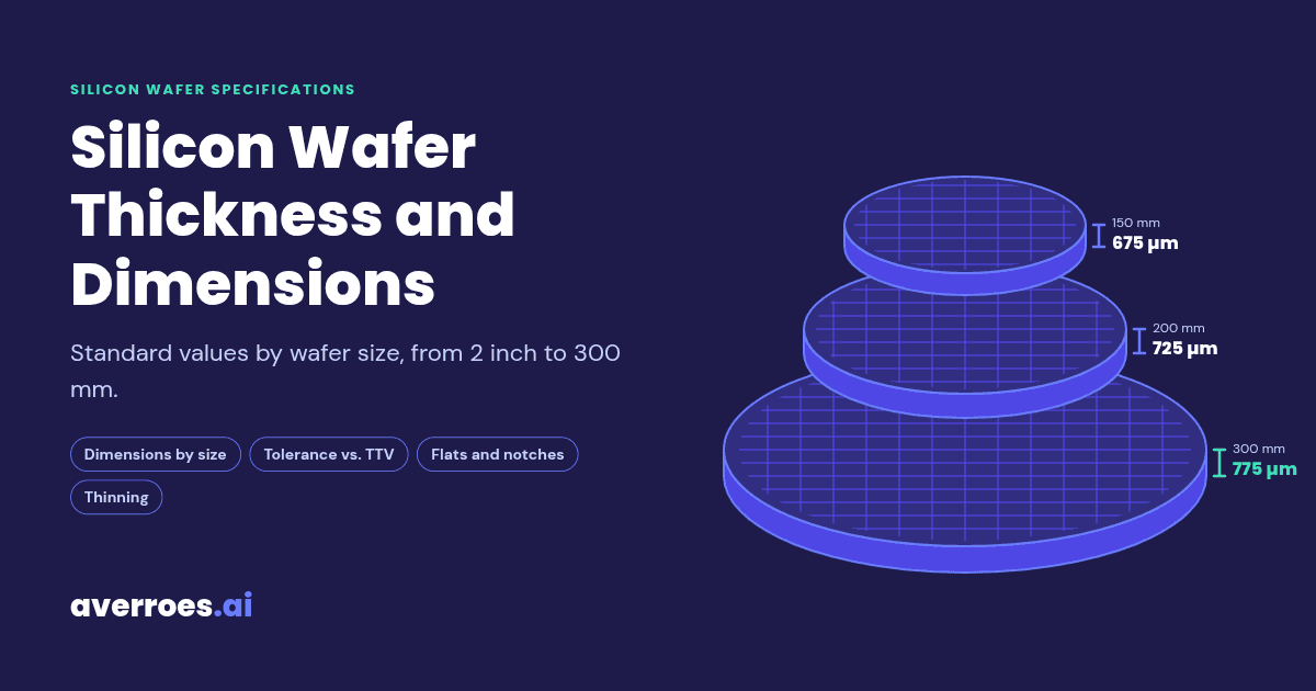
A standard 300 mm silicon wafer is 775 µm thick, and a 200 mm wafer is 725 µm thick, as nominal values under SEMI M1. See silicon wafer thickness for every wafer size, its tolerance and its weight.
How long does it take to make a silicon wafer?
Growing and cooling a single 300 mm ingot alone takes more than a day. Slicing, lapping, etching, polishing, cleaning and inspection add several more process steps, each with its own queue and measurement time. Total lead time depends on the supplier, the wafer type and whether an epitaxial layer is added.
Why are silicon wafers round?
Silicon wafers are round because the ingot grows as a cylinder from a rotating seed crystal, so slicing it produces discs. A round shape also spreads handling and thermal stress evenly around the edge, and it suits the spinning chucks used in coating, cleaning and polishing tools.
What is the difference between prime and test wafers?
Prime wafers meet the full dimensional, flatness and surface limits of SEMI M1 and are used to build product. Test and monitor wafers, specified under SEMI M8, carry looser limits and are used to qualify tools and monitor processes. Reclaimed wafers are used test wafers that are stripped and repolished.
What is a silicon wafer made of?
A silicon wafer is made of single-crystal silicon refined from quartz to 9N purity, with a small, controlled amount of dopant added during crystal growth. Boron makes p-type wafers and phosphorus makes n-type wafers. The dopant level sets the wafer’s resistivity.







Silicon wafers are made by purifying silicon to 9N electronic-grade polysilicon, growing it into a single-crystal ingot by the Czochralski or float-zone method, and slicing the ingot with a diamond wire saw. Each slice is then edge-profiled, lapped or ground flat, etched to remove saw damage, polished to a mirror finish, cleaned and inspected against SEMI M1 specifications before it ships to a fab.
Wafer manufacturing is Stage 02 of the 12-stage semiconductor manufacturing process. This guide from Averroes.ai, an AI visual inspection platform for manufacturers, maps each step to the specification it sets, the defect it can create and the tool that catches it.
Key Notes
The Wafer Manufacturing Process at a Glance
Silicon wafer manufacturing is the sequence of crystal growth, shaping and surface finishing steps that turns electronic-grade polysilicon into a polished, inspected substrate for chip fabrication. Each step sets at least one specification on the finished wafer. Each step can also leave a defect that a later step has to remove or an inspection tool has to catch.
Wafer manufacturing process: 10 steps
The diagram makes one point: defects are created at almost every step, but only a few steps carry an inspection that can see them. Most wafering defects are caught at final inspection, long after the step that created them.
Silicon Wafer Manufacturing Process, Step by Step
Silicon wafer manufacturing runs in 10 steps. The first three belong to the silicon ingot stage. Steps 4 to 10 form the wafer manufacturing stage proper, where the ingot becomes individual polished wafers.
1. Purify Silicon to Electronic-Grade Polysilicon
Electronic-grade polysilicon is silicon refined to 9N purity (99.9999999%), used as the feedstock for single-crystal growth. Quartz is first reduced to metallurgical-grade silicon in an arc furnace. That silicon is converted to trichlorosilane gas, distilled, and deposited back as solid silicon on heated rods in the Siemens process. The rods are broken into chunks sized for the crystal puller.
2. Grow a Single-Crystal Ingot
Single-crystal growth is the step that turns polysilicon chunks into an ingot with one continuous crystal lattice. Most wafers come from the Czochralski process, which pulls a rotating seed crystal from molten silicon held just above 1,414°C. Float-zone growth, which uses no crucible, serves high-resistivity wafers for power devices and detectors.
3. Shape the Ingot: Crop, Grind and Notch
Ingot shaping crops the seed and tail cones, grinds the body to an exact diameter, and grinds a notch along its length to mark crystal orientation for every downstream tool. The Czochralski process guide covers this step in detail.
4. Slice the Ingot With a Diamond Wire Saw
Wire saw slicing is the step that cuts the ingot into wafers, using a web of hundreds of parallel diamond-coated wires that move through the crystal at once. Slicing the whole ingot in one pass keeps wafer thickness consistent across the batch.
Every cut turns a slice of silicon into kerf dust. It also leaves a damaged layer several microns deep under each new surface. That layer holds microcracks and residual stress, and every later step through etching exists partly to remove it.
5. Profile the Edge
Edge profiling is the step that grinds the sharp rim of each sliced wafer into a rounded bevel with a defined shape. A sharp edge chips under handling. Chips shed silicon particles that can land on the device area inside the fab. A defined bevel also stops material from building up at the rim during later epitaxy and resist coating.
6. Lap or Double-Disk Grind
Lapping is a mechanical flattening step that grinds both faces of a wafer parallel, using an abrasive slurry between two rotating plates. Many 300 mm lines use double-disk grinding instead, which flattens both sides with fixed-abrasive wheels. Either way, the step removes most of the saw damage and waviness and brings the wafer close to final thickness.
7. Etch Away the Damaged Layer
Wafer etching is a chemical step that dissolves the mechanically damaged layer left by slicing and lapping. Wafers are etched in an acid mixture or an alkaline solution. Removing the damaged silicon also relieves the stress it carried, which protects the wafer from warping or cracking in later thermal steps.
8. Polish to a Mirror Finish
Wafer polishing is the chemical-mechanical step that turns an etched wafer into a mirror-finished surface flat enough for lithography. Most 300 mm wafers go through double-side polishing first, using a colloidal silica slurry and polyurethane pads on both faces at once. A final single-side polish then sets the device surface.
Polishing here is substrate preparation at the wafer supplier. It is not the between-layer chemical mechanical planarization (CMP) that runs dozens of times during wafer fabrication at Stage 03, though the chemistry is related.
9. Clean the Wafer
Wafer cleaning is the wet chemical sequence that removes particles, organic residue and metals before final inspection. Most lines run a variant of the RCA clean. SC-1, a mix of ammonia and hydrogen peroxide, lifts particles and organics. SC-2, a mix of hydrochloric acid and hydrogen peroxide, removes metals.
SC-1 also etches the surface very slightly. That can open crystal originated particles into surface pits, which a laser scanner counts much like real particles. This is where silicon ingot defects from Step 2 first become visible.
10. Inspect, Sort and Pack
Final wafer inspection is the gate where every wafer is scanned, measured and sorted against the customer specification before shipping. It is also the first point in the process where most wafering defects are seen at all.
Three tool types run here:
Passing wafers are packed in front-opening shipping boxes (FOSB) for transport to the fab.
The limit of this gate is physics. A laser scanner reports light scattering, not defect identity. A particle, a polishing pit and an opened COP can return similar signals. SEMI M50 defines how a scanner’s capture rate and false count rate are measured, and the false count rate decides how many good wafers get held for review. AI defect classification on the scanner, edge and macro images separates real defect classes from nuisance without changing the tools.
What Silicon Wafer Specifications Define a Prime Wafer?
A prime silicon wafer is a polished single-crystal wafer that meets the dimensional, flatness, surface and electrical limits in SEMI M1, with at least one chem-mechanically polished surface. SEMI M1 is the base specification that wafer suppliers and fabs build purchase orders on. Each fab then tightens individual limits for its own technology generation.
The reference values are anchors, not limits. The binding numbers live in each purchase specification built on SEMI M1, and they tighten with every node.
Geometry carries straight into yield. Bow and warp beyond the lithography chuck’s tolerance cause focus error across the exposure field, and poor site flatness does the same within a single die. See wafer bow and warp measurement for how these are measured and where the limits come from.
Not every wafer has to meet prime limits. Test and monitor wafers, specified under SEMI M8, carry looser limits and are used to qualify tools and monitor processes rather than to build product.
What Defects Form During Wafer Manufacturing?
Wafer manufacturing defects are geometric, edge and surface flaws introduced between slicing and packing. They are distinct from crystal defects, which are grown into the ingot before the first cut. Most wafering defects are created at one step and only detected several steps later.
Backside contamination is the defect most often underweighted in incoming specs. A particle on the back surface lifts the wafer on the lithography chuck, which shows up as front-side focus and overlay error. See backside wafer inspection for the tools and failure modes.
Crystal defects follow a different path. COPs, oxygen precipitates, slip and resistivity variation are set during ingot growth, not wafering. The Czochralski process guide covers where they come from, and silicon ingot defects covers how they surface downstream.
Where AI Inspection Fits in Wafer Manufacturing
AI defect classification is software that sorts the defects laser scanners, edge tools and macro tools already detect into real defect classes and nuisance, without new inspection hardware. In wafer manufacturing it matters at two gates.
The cost sits in the false count rate. SEMI M50 defines how to measure a scanner’s capture rate and false count rate, and the two trade against each other. Raise sensitivity to capture smaller defects and nuisance counts rise with it. Classification breaks that trade: the scanner stays at full sensitivity, and the model decides which detections are real.
Incoming wafer quality also sets the detection floor for everything after it. If incoming wafers carry a variable particle baseline, every inline scan during front-end wafer inspection inherits that noise.
Averroes.ai runs as an overlay on the laser scanners, edge and macro tools a supplier or fab already owns. It trains classification models from 20 to 40 labeled images per defect class, with no code, and deploys on premise so wafer image data stays inside the customer environment. Trending classified defects by lot, step and supplier with defect monitoring turns a recurring incoming defect into supplier feedback backed by evidence.
Still Reviewing Wafer Defects by Hand?
Test AI defect classification on your own incoming wafer images
Frequently Asked Questions
How are wafers made for semiconductors?
Semiconductor wafers are made by growing a single-crystal silicon ingot from electronic-grade polysilicon, slicing it with a diamond wire saw, and finishing each slice through edge profiling, lapping, etching, polishing and cleaning. Every wafer is then scanned for defects and measured for flatness before it ships to a chip fab.
How thick is a silicon wafer?
A standard 300 mm silicon wafer is 775 µm thick, and a 200 mm wafer is 725 µm thick, as nominal values under SEMI M1. See silicon wafer thickness for every wafer size, its tolerance and its weight.
How long does it take to make a silicon wafer?
Growing and cooling a single 300 mm ingot alone takes more than a day. Slicing, lapping, etching, polishing, cleaning and inspection add several more process steps, each with its own queue and measurement time. Total lead time depends on the supplier, the wafer type and whether an epitaxial layer is added.
Why are silicon wafers round?
Silicon wafers are round because the ingot grows as a cylinder from a rotating seed crystal, so slicing it produces discs. A round shape also spreads handling and thermal stress evenly around the edge, and it suits the spinning chucks used in coating, cleaning and polishing tools.
What is the difference between prime and test wafers?
Prime wafers meet the full dimensional, flatness and surface limits of SEMI M1 and are used to build product. Test and monitor wafers, specified under SEMI M8, carry looser limits and are used to qualify tools and monitor processes. Reclaimed wafers are used test wafers that are stripped and repolished.
What is a silicon wafer made of?
A silicon wafer is made of single-crystal silicon refined from quartz to 9N purity, with a small, controlled amount of dopant added during crystal growth. Boron makes p-type wafers and phosphorus makes n-type wafers. The dopant level sets the wafer’s resistivity.